Safety Logic Plus
The simple way to build a complex Safety Interlock® System without using a Safety PLC.
The Safety Logic Plus uses simple logic to achieve a fully-safe and custom Interlock system for laser safety.
- Eliminates the obsolescence associated with Safety PLC systems
- Lifetime of 20+ years, fully re-configurable throughout lifespan
- Hard wired, dual channel, monitored, relay based logic
- Very high safety integrity – PLe to ISO 13849-1 (equivalent to SIL3)
- Cost effective
- Fault finding made easy with CALM for SLP
Description
Logic for Interlock Systems
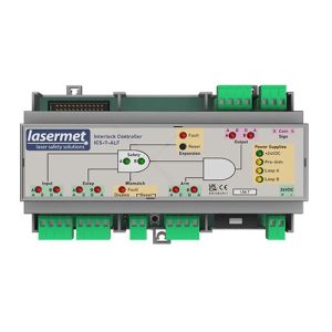
Lasermet’s Safety Logic Plus (SLP) is a simple, cost-effective and secure concept in which the logic configuration required for a safety Interlock® system is hardwired in a single logic enclosure. The system makes use of modules that receives input from all Interlock® switches.
The SLP System is capable of containing all of the logic functions for the safety Interlock®. Complicated permissions can be achieved through logic, only able to arm the laser via the Lasermet Interlock® Controller when all of the safe conditions have been met.
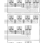
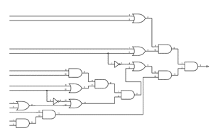
Safety Logic Plus
The diagram above shows the typical complexity and subsequent simplification of circuitry only in pictorial form. Some of the 32 connections in the complex diagram are wired together so that each diagram has the same number of inputs and outputs.
Customers can design and build complex safety Interlock® systems and virtually eliminate obsolescence as the Safety Logic Plus has 30+ years life expectancy. The simplified on-site installation techniques reduce installation time and costs while also simplifying testing and fault finding procedures.
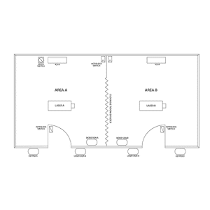
The Need for Safety Logic Plus
Standard simple Interlock® systems consist of a series of door contacts connected in series to form a safety loop. This information is sent back to Lasermet’s Interlock® controller.
However, with more powerful lasers and a greater number of them, it is even more critical that laser safety interlocks be installed at a low cost and that their logic be easily understood, maintained, and updated, especially when there are new lasers or changes to the facility.
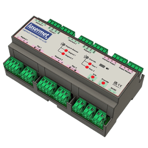
To meet this need, Lasermet developed the Safety Logic Plus concept, which is a non-processor-based fail-safe logic system that integrates all of the logical functions of the Interlock® system into a single enclosure. All that is required is to connect each door contact and other control to Safety Logic Plus via individual cables. The system’s logic function is carried out by interconnecting the internal logic modules in accordance with the logic diagram. A competent electrician can wire this.
- Installation, maintenance and testing is straightforward
- No specialist PLC training is required
- The design enables easy and fast fault finding
- Logic changes are done within the enclosure
INCREASED COMPLEXITY
Modern Interlock® systems have a tendency to be configurable in order to provide multiple modes of operation and varying coverage areas. Implementing such systems with point-to-point wiring between the various door contacts and controls within a building presents significant challenges for installation, testing, and fault-finding, raising installation and maintenance costs.
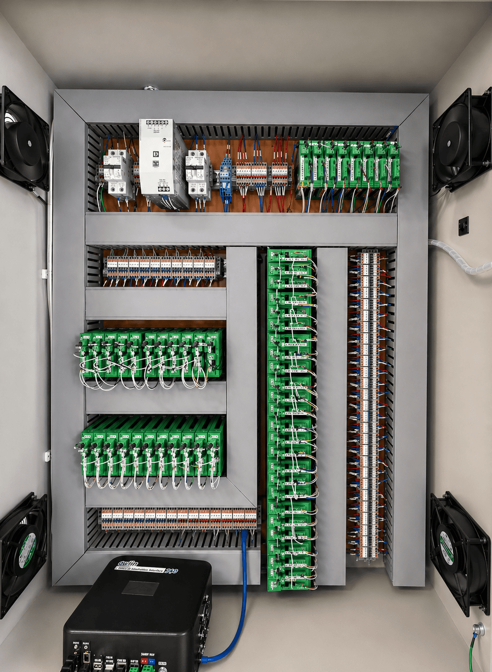
SIMPLICITY AND SAFETY THROUGH HARD-WIRED LOGIC
The wiring system can be simplified by using AND and OR gate modules to implement the basic logic. The components are all basic electrical components like hard wired jumper type connectors, relays, and LEDs.
SAFETY THROUGH DESIGN
To provide the logic function, the relay-based logic gates are connected using jumper leads. Because each module has its own LED, it is simple to inspect. Every module has a cross checking function applied to it, so that if it fails or there is no input to it, the laser will not arm. Throughout the system, double safety circuits are used.
- It is a fail-safe system
- It uses dual channels
- It has full cross checking of all circuits
- The laser will not arm until all circuits are checked on both channels and all conditions are satisfied including self-checking.
ELIMINATE OBSOLESCENCE
This logic system eliminates the obsolescence issues that have already emerged with PLC-based systems, which rely on interface standards and operating systems that rapidly become obsolete. It does not require any programming languages, software, or a computer with an operating system, and thus is unlikely to become obsolete.
Through its fail-safe design, Safety Logic Plus eliminates a variety of issues. All wires are fed directly back to the enclosure where the logical functions are determined from all remote door locks or switches.
- No software
- No Programmable Logic Control
- No operating system
- No specialist training
SIMPLE CUSTOM DESIGN
The design is such that any competent engineer who can follow the wiring diagram is able to check, test, modify or replace any modules or wiring. He does not require any diagnostic software, programming skills, any specific operating systems or other potentially obsolete test equipment. The system can be adapted, upgraded and modified at one point within Safety Logic Plus.
- All safety switches are connected to the enclosure.
- The enclosure houses all logic functions.
- All logic functions are performed using modules.
The Lasermet Solution
Alterations to existing conventional complex site wiring system installations can be difficult and time consuming and therefore expensive. Safety Logic Plus is a cost effective solution.
Often faults can be identified almost immediately due to the design, making fault-finding a breeze.
Loss of cable identification can often happen to cables during either installation or during the working life of the system when maintenance or modifications to the building or the wiring itself takes place. Safety Logic Plus simplifies identifying unmarked installed cables.
The SLP System greatly helps with maintenance of systems and elimination of bugs associated with any software used especially Programmable Logic Controllers. As there is no software it cannot go obsolete. This includes the software itself, the program type (including language) and the operating system on which it runs. Any maintenance or changes are easily implemented for the anticipated lifetime of the equipment which is expected to exceed 30 years.

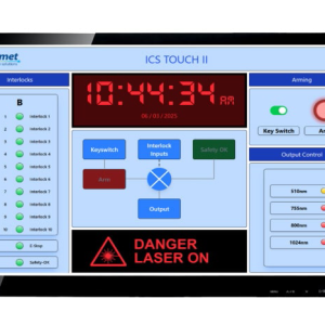
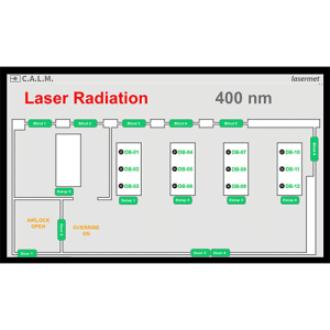
CALM for Safety Logic Plus Systems
With the CALM System, Safety Logic Plus circuits are simplified to achieve complex system functionality while easily displaying system status at a glance.
With the SLP View on the CALM monitor, users can view traceable logic circuits making fault-finding a breeze for large systems. The possibilities are endless.